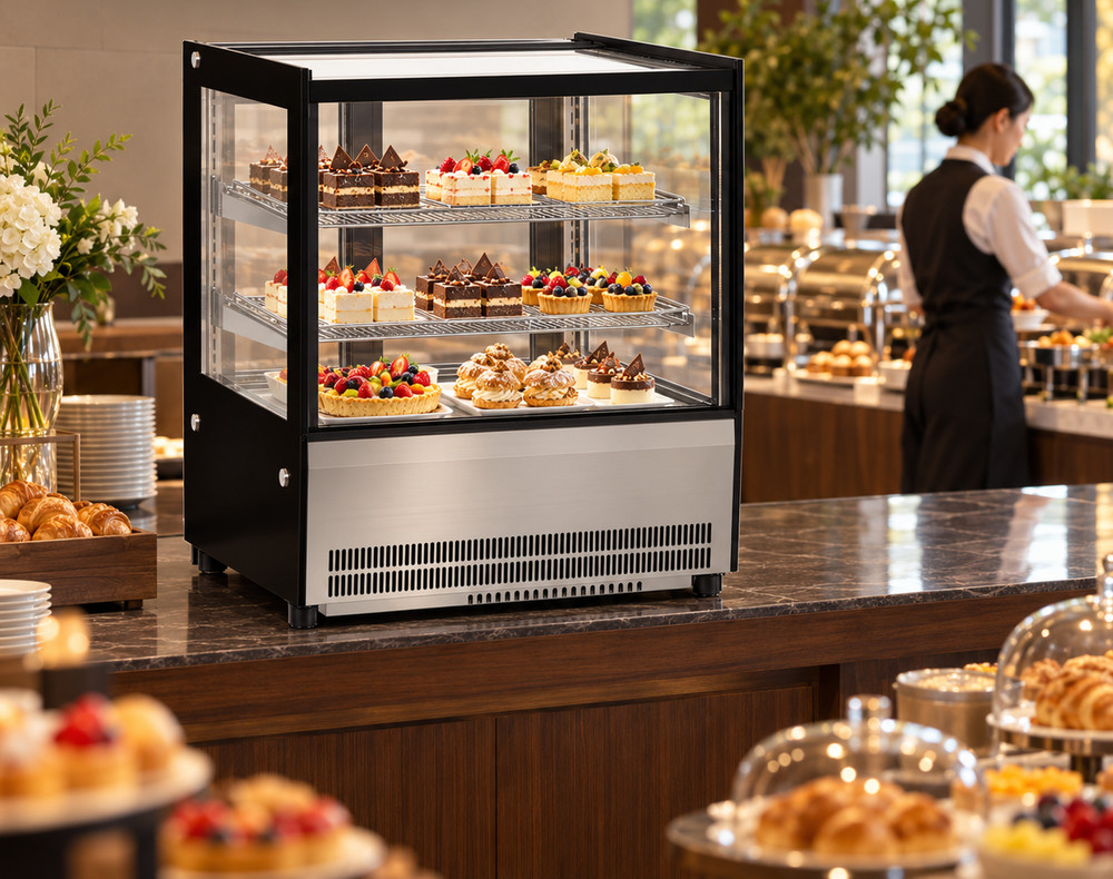
What is included in the display fridge size CAD download?
The download contains six outside cabinet footprints: GN-660RT, GN-900RT, GN-1200RT, GN-1000L, GN-1200L and GN-1200RF2. Each model has its own named layer, a rectangular top view, a labelled front edge and a width, depth and height note. The RT models are countertop displays; the L and RF2 models are floor-standing equipment. Their published overall dimensions supply the rectangle coordinates. The file uses one drawing unit per millimetre.
The six outlines are arranged as a selection sheet with space between them. Move the selected outline into your project drawing rather than interpreting the sheet as an equipment lineup. Keep its model label and height note with it. The accompanying table links each outline to the complete product record, including photographs and specifications. This gives the person preparing the room plan a model reference as well as a shape.
How do I check the import scale before placing a cabinet?
Open or import the DXF into a drawing using millimetres. Measure the GN-1200RT rectangle: its horizontal side should read 1200 and its perpendicular side 530. Check GN-1000L as a second reference; its footprint is 1000 by 740 mm. Keep these measurements in model space while arranging the equipment, then set the printed view scale separately in your drawing software.
If your project uses metres, 1200 mm becomes 1.2 m and 530 mm becomes 0.53 m; the millimetre coordinates require a factor of 0.001 when converted into metre coordinates. For an inch-based project, divide the millimetre values by 25.4. Check an actual rectangle after conversion rather than relying on a file preview. A printed sheet fitted to the paper can change physical scale while retaining the same dimension text, so use the drawing measurement tool for the import check.
Which footprint should I place on the service counter?
GN-660RT, GN-900RT and GN-1200RT have widths of 660, 900 and 1200 mm. Each shares a 530 mm depth and a 730 mm cabinet height. Put the chosen rectangle inside the outline of the supporting furniture, then show the staff approach to its rear sliding doors. The footprint describes the cabinet body; draw the counter, nearby coffee equipment and packing surface as separate objects.
For an illustrative 1800 mm counter run, the three cabinet widths leave 1140, 900 or 600 mm of gross frontage respectively. These subtraction results precede installation spacing and the rest of the counter equipment. On an illustrative 900 mm-high support, each RT cabinet reaches 1630 mm above the floor. Add that elevation to the drawing so the customer sightline and overhead furniture are reviewed alongside the top view. The export labels the cabinet height without adding the supporting furniture.
How do the floor-standing outlines differ from the RT cabinets?
GN-1000L measures 1000 × 740 × 1400 mm, and GN-1200L measures 1200 × 740 × 1400 mm. Both belong to the open-front grab-and-go series. GN-1200RF2 measures 1200 × 730 × 1200 mm and records two sliding doors on the service side. Their top-view rectangles let you compare the body depth, while the model labels keep the different heights and access arrangements attached to the choice.
At the same 1200 mm width, GN-1200L extends 210 mm deeper than GN-1200RT; GN-1200RF2 extends 200 mm deeper. A counter rectangle and a floor-standing cabinet rectangle may therefore need different positions on the room plan even when their frontages match. Draw the intended customer and staff sides before moving equipment into place. For RF2, mark the service side and add the access space from the installation drawing as a separate layer; the footprint file contains the closed outside body.
Does the DXF include installation or tray-fit dimensions?
The geometry covers published overall width and depth, with overall height recorded in text. Ventilation spacing, service access, door travel, internal shelves, feet and connection positions require their own model documents. Add those dimensions to the project drawing after reviewing the selected configuration. A 1200 × 530 mm rectangle represents the GN-1200RT exterior; it does not establish the length of a shelf inside the glass.
Give the inquiry recipient the proposed position and full model code, then request the dimensional drawing relevant to that unit. Keep the original cabinet outline on its named layer and place installation information on another identifiable layer. This lets a reviewer distinguish the catalogue body dimensions from the returned installation requirements. If the drawing changes an overall dimension, record the document reference and revision beside the equipment line before updating the outline.
How should the download be used in a multi-cabinet plan?
Copy an outline for each cabinet in the intended arrangement and give every copy a project line reference. Two GN-900RT bodies occupy 1800 mm of combined frontage before any spacing. One GN-1200RT plus one GN-660RT occupies 1860 mm. On an illustrative 2400 mm run, those combinations leave 600 and 540 mm respectively. Draw the remaining surface and any required gaps explicitly rather than stretching a cabinet rectangle to fill the run.
Keep each copied model label readable. Separate cabinet bodies retain separate interiors and access positions even when the plan shows them side by side. Mark the packing area, collection point and serving approach on the room drawing, then review the proposed arrangement against the returned installation documents. Save the downloaded selection sheet separately from your edited project so the original model dimensions remain available for comparison.
What should I send with a marked-up CAD plan?
Send Shaanxi Jinyu Kitchenware Co., Ltd. (陕西金宇厨具有限公司) the selected model codes, equipment quantities, destination and a dimensioned plan showing the cabinet positions. Include support heights for countertop models, overhead obstructions, access sides and the local electrical supply. Attach a PDF view alongside the editable drawing so the intended arrangement and equipment line references can be read without opening the CAD file.
Ask the response to identify the selected configuration and its dimensional and installation documents. Keep proposed alternatives on separate equipment lines, with their own footprints and document references. Review any width, depth, height or access change against the room drawing before replacing the original selection. The linked model pages provide the published specifications used for these outlines; the marked-up plan explains the proposed site and how the equipment is intended to be arranged.