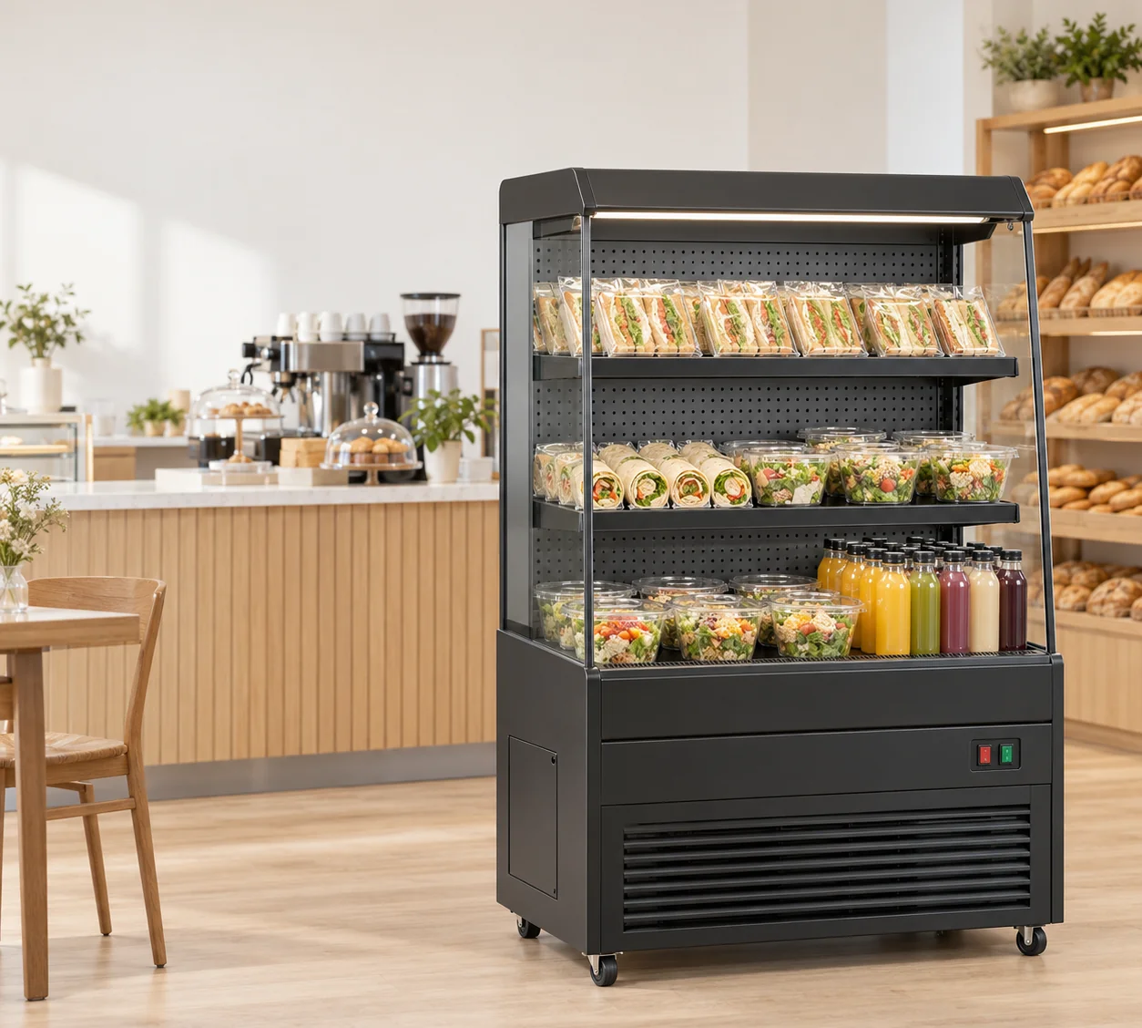
What belongs on a grab-and-go counter service connection plan?
Put the cabinet outline, site connection points and the supplier's connection drawing on the same measured plan. Give the counter position an identifier, such as G1, and retain the complete JINYU model code. Record the existing site points separately from connections described for the offered equipment. A nearby socket or drain is a site observation; its presence does not establish that it serves the selected cabinet.
Start with the four published cabinet outlines below. GN-900L and GN-900LG share a 900 × 740 mm footprint, while their heights differ. GN-1200L adds 300 mm of width. GN-1000FRO is 1000 × 730 mm. These dimensions locate bodies on the drawing. Ask for the connection positions and installation envelope for the offered configuration before drawing a connected arrangement.
How do I give the site and cabinet drawings the same measurement origin?
Choose a fixed, visible corner as the plan origin and identify it in an overall photograph. For the worked example, X runs right along a wall, Y runs out into the room and Z measures height above the finished floor. Record all distances in millimetres. Mark which edge faces customers so a drawing viewed from behind cannot silently reverse left and right.
The illustrative cabinet rear-left corner is X=300, Y=200. A site point S1 is X=1500, Y=100, Z=350. These are buyer survey coordinates, not JINYU connection locations or installation clearances. Keep Z on the elevation even when two points overlap in plan. If the room drawing uses another origin, record the translation explicitly instead of copying its numbers into a different coordinate system.
How does changing cabinet width affect a fixed site point?
Using the same example origin, GN-900L extends from X=300 to X=1200 and from Y=200 to Y=940. The site point at X=1500 is 300 mm beyond the cabinet's right edge in plan. Replacing it with GN-1200L moves that right edge to X=1500, directly level with the site's X coordinate. The site point itself has not moved.
GN-1000FRO ends at X=1300 and Y=930 in this comparison, leaving a 200 mm difference between its right edge and S1's X coordinate. The table reports coordinate differences only. They do not describe cable length, pipe length or an accessible route. A fitting can project beyond the body, and the connection route can turn around an obstruction. Overlay the returned model drawing before selecting the final position.
What should the supplier identify about condensate and drainage?
Ask how the offered configuration handles condensate, then request the applicable connection or collection arrangement in writing. Have the response identify any supplied components and any work allocated to the site. The model records used here do not specify drain outlet positions, fitting dimensions or a pipe route. Copying an outlet position from another cabinet would introduce a new equipment claim without a matching document.
For a documented connection, request its side, height, projection and measurement reference. For a documented collection arrangement, request the location and access procedure. Keep the supplier's original field names with the drawing revision. Attach the site's measured drain information as a separate layer and ask the installation contact to review the proposed relationship. Record the resulting arrangement against G1 and the selected model.
How do electrical points fit into the same site plan?
Give electrical points their own identifiers and record the site information supplied by the installation contact. All four models in this table list 220-240V/50Hz; their recorded rated powers range from 470 W to 950 W. Keep each rating on its own equipment row. Those catalogue entries do not identify plug orientation, cable exit position or a connection route behind adjacent furniture.
Request the electrical connection drawing for the offered configuration and mark the corresponding point on the elevation. Show fixed panels and neighbouring equipment that could hide access. A site socket height and a cabinet connection height are different measurements even when they appear close in a photograph. Send both drawings together for review, retaining separate references for the site observation and the equipment specification.
How should I record a route that passes behind the counter?
Draw the actual proposed path as a sequence of labelled segments, using the supplier's connection location and the site's endpoint. Show the obstacles beside that path: skirting, columns, cabinet feet, fixed plinths and other services visible in the survey. Photograph each turn and mark it on the plan. Do not replace a route drawing with the straight-line distance between the cabinet rectangle and the site point.
Ask for the space needed to reach and service the documented arrangement, then show that space on the same plan. Keep removable panels distinguishable from fixed furniture. If the cabinet position changes, revisit the path and access views rather than translating only the rectangle. A wider cabinet can cover a previously visible site point even when the wall and supply location remain unchanged.
What should I send with a service connection inquiry?
Send the selected model, position identifier, dated plan, elevation, coordinate origin photograph and site-point register. Add the cabinet connection drawing when supplied, keeping its document revision visible. Use the response worksheet below to separate the buyer's observation from the supplier's equipment description and the proposed installed route. This lets the next reply address a named point rather than an unidentified area behind the display.
Address the inquiry to JINYU, Shaanxi Jinyu Kitchenware Co., Ltd. (陕西金宇厨具有限公司). Request a revised overlay whenever the model, orientation or offered configuration changes. Retain the previous drawing with its date so the project team can see which connection assumptions changed. Hand over the selected cabinet record, returned installation documents and current site plan as one identified set.