What does the printable display fridge size sheet contain?
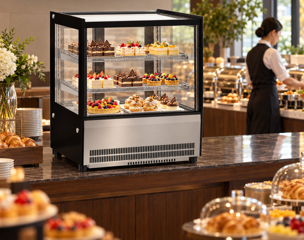
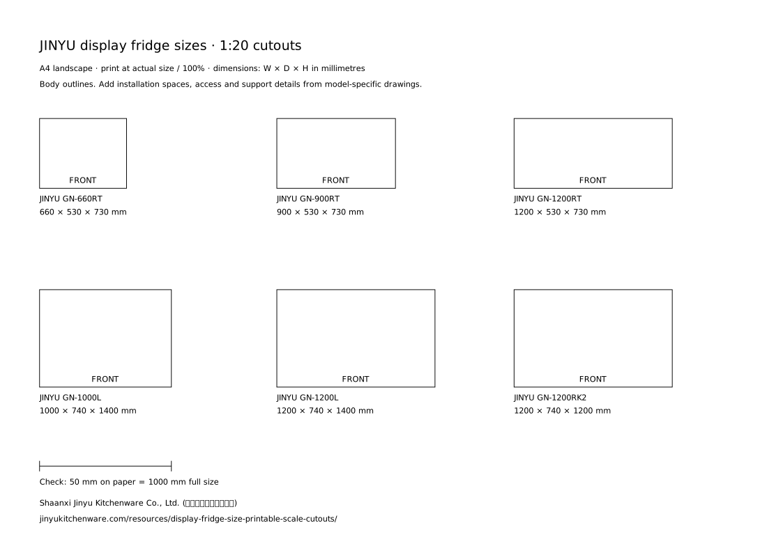
The A4 landscape sheet contains six labelled top-view rectangles at 1:20 scale. GN-660RT, GN-900RT and GN-1200RT are countertop cake displays. GN-1000L and GN-1200L are open-front grab-and-go cabinets, while GN-1200RK2 is a straight-glass cake display. Each rectangle uses the published outside width and depth of its named model. The label below it records the full width, depth and height in millimetres.
Use the sheet when reviewing a paper layout with colleagues who do not work in CAD. Cut along the rectangle edges and keep the separate model labels beside the selected shapes. The sheet shows alternatives in a grid for cutting; those positions do not represent a proposed shop arrangement. Photographs and complete model records are linked in the table below.
How do I print the cutouts at the correct scale?
Download the SVG, open it in a browser or drawing application, and select A4 landscape paper. Print at actual size or 100 percent. Switch off fit-to-page scaling and review any printer setting that reduces oversized pages. The file specifies a physical page size of 297 × 210 mm, with its content placed inside a 15 mm margin. Printer software still controls the final output size.
Measure the horizontal calibration line with a ruler after printing. Its endpoints must be 50 mm apart, representing 1000 mm at full size. Also measure the GN-1200RT rectangle: its width should be 60 mm and its depth 26.5 mm. If either check differs, adjust the print settings and print again before comparing the shapes with a floor plan. A correct-looking dimension label does not establish the physical print scale.
Can I place these shapes on an existing room drawing?
Use the cutouts on a room drawing printed at the same 1:20 scale. At that scale a measured 2000 mm wall is 100 mm long on paper, and a 900 mm opening is 45 mm. Check a known dimension on the room drawing independently of the cutout sheet. An unscaled estate-agent sketch or a photograph of a plan needs its own scale check before the pieces can represent real space.
Mark the customer-facing edge using the FRONT label, then rotate the cutout to match the intended display direction. Draw the counter, walls, pillars and adjacent equipment on the room plan. Keep paper pieces movable while comparing positions. Once an arrangement is selected, record the full model code and actual millimetre dimensions on the project drawing so that a photocopy or resized scan cannot silently change the equipment schedule.
What size differences become visible on the paper sheet?
The three RT cabinets share a 530 mm depth and 730 mm body height. Their 660, 900 and 1200 mm widths become 33, 45 and 60 mm on the sheet, while each depth becomes 26.5 mm. Moving from GN-900RT to GN-1200RT therefore adds 15 mm to the paper footprint, corresponding to 300 mm of actual frontage. Compare that change with the packing surface and payment position already drawn on the counter.
GN-1000L measures 1000 × 740 × 1400 mm and GN-1200L measures 1200 × 740 × 1400 mm. Their cutouts are 50 × 37 mm and 60 × 37 mm. GN-1200RK2 has the same 1200 × 740 mm footprint as GN-1200L but a recorded height of 1200 mm. Keep their labels separate: equal top-view rectangles can represent cabinets with different heights, access arrangements and display formats.
How do I account for support height and working space?
For the countertop RT models, add the measured support height to the 730 mm cabinet height when preparing an elevation. On an illustrative 900 mm support, the cabinet top is 1630 mm above the floor, or 81.5 mm on a separate 1:20 elevation. The paper top view cannot show this vertical relationship. Record overhead shelving and signs on the elevation alongside the cabinet top.
The rectangle describes the closed cabinet body. Draw the model-specific installation spaces, staff access and loading movements separately using the returned installation and access drawings. Do the same for the route to the final position using shipment package dimensions. The cutout dimensions do not supply package size, door-opening envelopes or usable shelf measurements. Keep each of those records attached to the selected model rather than deriving them from the body outline.
What should I send after comparing the cutouts?
Photograph or scan the selected arrangement with the wall dimensions, scale reference and full model labels visible. Add the project position, requested quantity and the dimensioned room drawing. State whether an RT cabinet will sit on existing furniture and include its measured height and support details. For an L or RK2 cabinet, identify the floor position and orientation of the customer and staff sides.
Send the shortlist to JINYU with the model-specific questions that remain: installation spacing, shelf layout, access drawings, site connection documents or shipment dimensions. Retain the returned drawing revision with the chosen layout. If the proposed model changes, replace its paper shape and label together, then review depth and height as well as width. For a digital drawing workflow, use the linked millimetre DXF guide and check the imported dimensions in the drawing software.